
IoT Based LPG Gas Monitoring

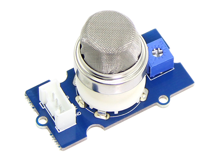
MQ-5 Module(Overview)

In this tutorial, will learn, how to interface MQ-5 Module with Node Mcu(ESP8266).

The Grove - Gas Sensor(MQ5) module is useful for gas leakage detection (in home and industry). It is suitable for detecting H2, LPG, CH4, CO, Alcohol. Due to its high sensitivity and fast response time, measurements can be taken as soon as possible. The sensitivity of the sensor can be adjusted by using the potentiometer.

MQ-5 Module(backside)

Components Required
  • NodeMcu(ESP8266) 
  • MQ-5 LPG SENSOR Module 
  • Few male to female connecting wires 
  • Breadboard 
Follow the image below for circuit connection reference:-
In this circuit, we have connected the A0 pin of the MQ-5 to the A0 pin of the NodeMcu module and D0 pin remain disconnected.
After making the circuit dump the code given below:-

// Karkhana Report
// Analyse the volume of the gas using thingspeak.com
// Hardware: NodeMCU,MQ-5

#include <ESP8266WiFi.h>
String apiKey = "Enter the API key"; // Enter your Write API key from ThingSpeak
const char *ssid = "Enter ssid"; // replace with your wifi ssid and wpa2 key
const char *pass = "Enter password";
const char* server = "api.thingspeak.com";
WiFiClient client;
void setup()
{
Serial.begin(115200);
delay(10);
Serial.println("Connecting to ");
Serial.println(ssid);
WiFi.begin(ssid, pass);
while (WiFi.status() != WL_CONNECTED)
{
delay(500);
Serial.print(".");
}
Serial.println("");
Serial.println("WiFi connected");
}
void loop()
{
float h = analogRead(A0);
if (isnan(h))
{
Serial.println("Failed to read from MQ-5 sensor!");
return;
}

if (client.connect(server, 80)) // "184.106.153.149" or api.thingspeak.com
{
String postStr = apiKey;
postStr += "&field1=";
postStr += String(h);
postStr += "\r\n\";
client.print("POST /update HTTP/1.1\n");
client.print("Host: api.thingspeak.com\n");
client.print("Connection: close\n");
client.print("X-THINGSPEAKAPIKEY: " + apiKey + "\n");
client.print("Content-Type: application/x-www-form-urlencoded\n");
client.print("Content-Length: ");
client.print(postStr.length());
client.print("\n\n");
client.print(postStr);
Serial.print("Gas meter");
Serial.print(h);
Serial.println("%. Send to Thingspeak.");
}
client.stop();
Serial.println("Waiting...");

// thingspeak needs minimum 15 sec delay between updates, I've set it to 30 seconds
delay(3000);
}


After dumping the code we can check our output in the serial monitor as well as in the thingspeak blogging channel chart graphically as shown below:-


As you can see from the above logging figure we can check the LPG gas rate of Karkhana.

Thinking?
Join our hands-on training courses.
To know more visit us at Karkhana Makerspace

Comments

Popular posts from this blog

LED Brightness Control using Touch Sensor and ARM

Hey Folks, In this tutorial, we will learn, how to change  the intensity of light using touch sensor the ARM (FRDM-KL25Z). INTRODUCTION The FRDM-KL25Z is an ultra-low-cost development platform for Kinetis L Series KL1x (KL14/15) and KL2x (KL24/25) MCUs built on ARM® Cortex™-M0+ processor.  The FRDM-KL25Z has been designed by NXP in collaboration with mbed for prototyping all sorts of devices, especially those requiring the size and price point offered by Cortex-M0+ and the power of USB Host and Device. The FRDM-KL25Z is supported by a range of NXP and third-party development software. It is packaged as a development board with connectors to break out to stripboard and breadboard and includes a built-in USB FLASH programmer.               FEATURES NXP KL25Z Kinetis KL2x MCU (MKL25Z128VLK4) High-performance ARM® Cortex™-M0+ Core 48MHz, 16KB RAM, 128KB FLASH USB (Host/Device) SPI (2) I2C (2) UART (3) PWM (TPM) ...

Arduino Based Audio Spectrum Analyzer Project

This Video will illustrate you how to visualize audio left and right signals in bar-graph in 16X2 LCD Display using Arduino. Components Required: 1. Arduino UNO 2. 16X2 LCD Display 3. 3.5mm Audio Jack 4. Jumper Wires   Connection Diagram: Video Link Arduino Code #include <LiquidCrystal.h> #include <fix_fft.h> #define DEBUG 0 #define L_IN 1 // Audio input A0 Arduino #define R_IN 0 // Audio input A1 Arduino const int Yres = 8; const int gain = 3; float peaks[64]; char im[64], data[64]; char Rim[64], Rdata[64]; char data_avgs[64]; int debugLoop; int i; int load; LiquidCrystal lcd(11, 10, 7, 6, 5, 4); // pins to LCD // Custom CHARACTERS byte v1[8] = {   B00000, B00000, B00000, B00000, B00000, B00000, B00000, B11111 }; byte v2[8] = {   B00000, B00000, B00000, B00000, B00000, B00000, B00000, B11111 }; byte v3[8] = {   B00000, B00000, B00000, B00000, B00000, B11111, B11111, B11111 }; byte v4[8] = {   B0...

Webcam Interfacing with Raspberry Pi

This tutorial is about the clicking photos and recording videos using "Logitech Webcam C110 with Raspberry Pi 3 Model B" Component Required: Rasberry Pi 3 Model B  Logitech Webcam C110  Adapter Charger micro USB-b Type 5v,2Amp  Connection Diagram: Step 1: Create a new folder First, we create a new folder just to store your photo and videos separately. Open the terminal. Command for creating new folder is "mkdir folder name" Step 2: Check everything is up-to-date To update your Raspberry Pi command is " sudo apt-get update ". And to upgrade your Raspberry Pi command is " sudo apt-get upgrade". Step 3: Check SSH and Camera enabled To make sure SSH and Camera enabled. Follow these two-steps. By this command, you can configure your SSH and Camera " sudo raspi-config ". Enable SSH. Enable Camera. Step 4: Check connection of Camera Make sure the camera is connected. Then run this command to make sure...