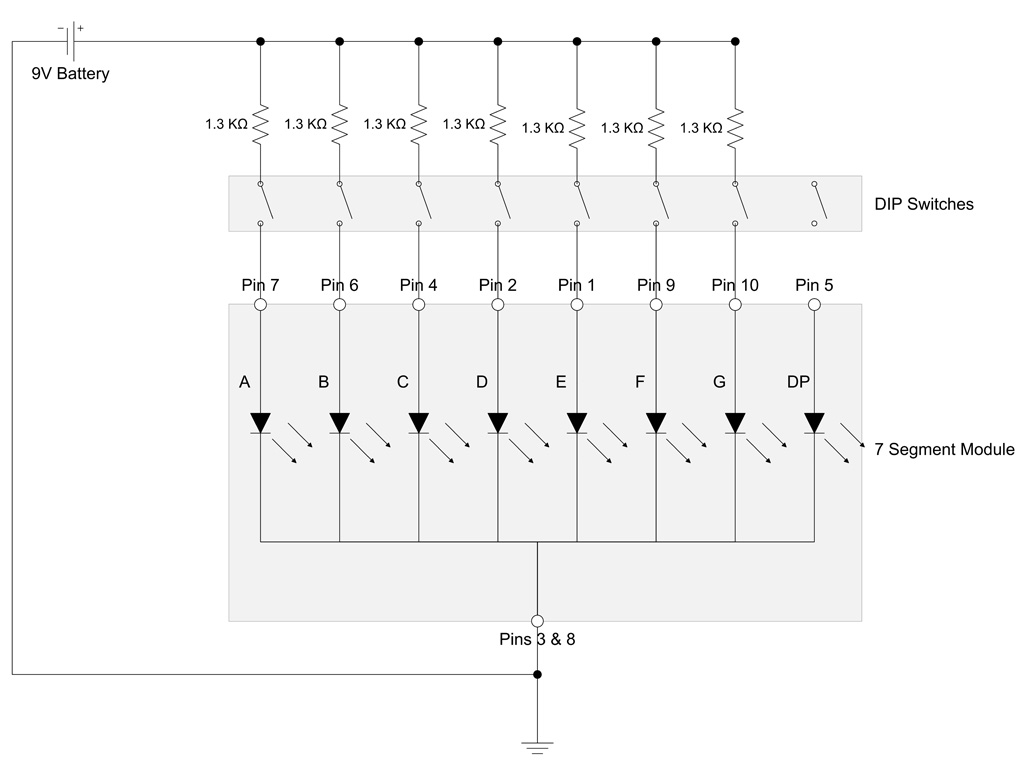
In this tutorial, we will learn how to interface a 7 SEGMENT DISPLAY with Arduino. A 7 SEGMENT DISPLAY consists of 8 LEDs and 10 pins,2 common pins are shorted and supplied with 5 volts from Arduino through a resistor and other 8 pins are connected to digital and analog pins.
7 Segment Display can act as a substitute for LCDs if we want to display numbers.
Shown below is the internal architecture of a 7 segment display.
Now let’s interface the 7 SEGMENT DISPLAY.
Components required
- Arduino Uno 1No.
- 7 Segment Display 1No.
- Resistors 1No. 100 ohms
- Connecting Wires
- Breadboard
There are two types of LED 7-segment display
- The common cathode (CC)
- Common anode (CA)
In CC type the cathode of all the LEDs is connected together and similarly in CA type.
In CC type we have to ground the common cathode pin and power up segments to illuminate it, the reverse happens for CA types. Here we have to power up the common anode pin and provide ground to segments according to our requirements of illuminations.
The below code can be used to display digits from Zero to Nine.
void setup()
{
pinMode(2,OUTPUT);
pinMode(3,OUTPUT);
pinMode(4,OUTPUT);
pinMode(5,OUTPUT);
pinMode(6,OUTPUT);
pinMode(7,OUTPUT);
pinMode(8,OUTPUT);
pinMode(9,OUTPUT);
digitalWrite(2,HIGH);
digitalWrite(3,HIGH);
digitalWrite(4,HIGH);
digitalWrite(5,HIGH);
digitalWrite(6,HIGH);
digitalWrite(7,HIGH);
digitalWrite(8,HIGH);
digitalWrite(9,HIGH);
}
void loop()
{ // ZERO
digitalWrite(2,LOW);
digitalWrite(3,HIGH);
digitalWrite(4,LOW);
digitalWrite(5,LOW);
digitalWrite(6,LOW);
digitalWrite(7,LOW);
digitalWrite(8,LOW);
digitalWrite(9,LOW);
delay(1000);
// Zero off
digitalWrite(2,HIGH);
digitalWrite(3,HIGH);
digitalWrite(4,HIGH);
digitalWrite(5,HIGH);
digitalWrite(6,HIGH);
digitalWrite(7,HIGH);
digitalWrite(8,HIGH);
digitalWrite(9,HIGH);
delay(1000); // ONE
digitalWrite(4,LOW);
digitalWrite(6,LOW);
delay(1000);
//1 off
digitalWrite(4,HIGH);
digitalWrite(6,HIGH);
delay(1000);
//2 0N
digitalWrite(2,LOW);
digitalWrite(3,LOW);
digitalWrite(5,LOW);
digitalWrite(6,LOW);
digitalWrite(7,LOW);
delay(1000);
//2 0ff
digitalWrite(2,HIGH);
digitalWrite(3,HIGH);
digitalWrite(4,HIGH);
digitalWrite(5,HIGH);
digitalWrite(6,HIGH);
digitalWrite(7,HIGH);
digitalWrite(8,HIGH);
digitalWrite(9,HIGH);
delay(1000);
//3 0n
digitalWrite(2,LOW);
digitalWrite(3,LOW);
digitalWrite(5,LOW);
digitalWrite(7,LOW);
digitalWrite(8,LOW);
delay(1000);
//3 0ff
digitalWrite(2,HIGH);
digitalWrite(3,HIGH);
digitalWrite(5,HIGH);
digitalWrite(7,HIGH);
digitalWrite(8,HIGH);
delay(1000);
//4 on
digitalWrite(3,LOW);
digitalWrite(4,LOW);
digitalWrite(5,LOW);
digitalWrite(8,LOW);
delay(1000);
//4 0ff
digitalWrite(3,HIGH);
digitalWrite(4,HIGH);
digitalWrite(5,HIGH);
digitalWrite(8,HIGH);
delay(1000);
//5 0n
digitalWrite(2,LOW);
digitalWrite(4,LOW);
digitalWrite(5,LOW);
digitalWrite(7,LOW);
digitalWrite(8,LOW);
delay(1000);
//5 off
digitalWrite(2,HIGH);
digitalWrite(4,HIGH);
digitalWrite(5,HIGH);
digitalWrite(7,HIGH);
digitalWrite(8,HIGH);
delay(1000);
//6 0n
digitalWrite(2,LOW);
digitalWrite(4,LOW);
digitalWrite(5,LOW);
digitalWrite(6,LOW);
digitalWrite(7,LOW);
digitalWrite(8,LOW);
delay(1000);
//6 off
digitalWrite(2,HIGH);
digitalWrite(4,HIGH);
digitalWrite(5,HIGH);
digitalWrite(6,HIGH);
digitalWrite(7,HIGH);
digitalWrite(8,HIGH);
delay(1000);
//7 0n
digitalWrite(2,LOW);
digitalWrite(3,LOW);
digitalWrite(8,LOW);
delay(1000);
//7 off
digitalWrite(2,HIGH);
digitalWrite(3,HIGH);
digitalWrite(8,HIGH);
delay(1000);
//8 on
digitalWrite(2,LOW);
digitalWrite(3,LOW);
digitalWrite(4,LOW);
digitalWrite(5,LOW);
digitalWrite(6,LOW);
digitalWrite(7,LOW);
digitalWrite(8,LOW);
delay(1000);
//8 off
digitalWrite(2,HIGH);
digitalWrite(3,HIGH);
digitalWrite(4,HIGH);
digitalWrite(5,HIGH);
digitalWrite(6,HIGH);
digitalWrite(7,HIGH);
digitalWrite(8,HIGH);
delay(1000);
//9 0n
digitalWrite(2,LOW);
digitalWrite(3,LOW);
digitalWrite(4,LOW);
digitalWrite(5,LOW);
digitalWrite(8,LOW);
delay(1000);
//9 0ff
digitalWrite(2,HIGH);
digitalWrite(3,HIGH);
digitalWrite(4,HIGH);
digitalWrite(5,HIGH);
digitalWrite(8,HIGH);
delay(1000);
}
Video
Now try this out with multiple 7 segment displays.

- You can also use IC 7446 which is a BCD to 7 segment decoder by which you can display all your digits with the combination of four inputs.Connect the IC as shown below.


Comments