
Getting Started with Arduino


Sudolearn Technologies - What is Arduino
What is Arduino?
Arduino is basically an open source electronics platform which is having easy to use hardware and software implementation. It’s a micro-controller interfaced with other vital components like programmer ICs, voltage regulator etc.

With the help of this, we can interface various input (sensors) and output (LED's) components.

Why Arduino?
Arduino is not just a micro-controller it is also interfaced with several other components which make the job of the user very simple.
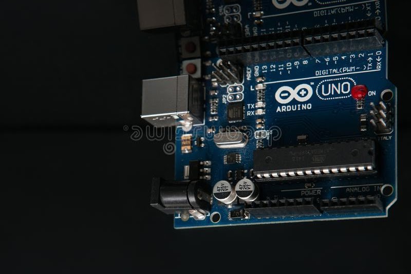
Arduino Summer Training
Arduino Uno Pin-Out

How Arduino works?
An input of 5v is given to the board using a USB cable (not necessary) through a laptop or any other convenient power source.
Microcontrollers are usually programmed through a programmer unless we have a firmware in our microcontroller that allows installing new firmware without any external programmer. This is bootloader.
All the controllers present in UNO are from ATMEL Semiconductor (Now acquired by Microchip).
We have a programming IC in Arduino which does the conversion from USB to serial.
It is available in various variants like in the original Arduino we have Atmega16, in the Indian Arduino we have CP2102 manufactured by Si-Labs and we have CH340 programmer in Arduino Nano/other.
The easiest way to control the software part is using Arduino IDE. The environment is written in Java and based on processing and other open-source software. The board is programmed in simple C programming through IDE.
General Block Diagram of Arduino

The above is a block diagram of Arduino UNO.

Advantages Include:
  • Since it’s an open-source platform we can get full access to everything including libraries, internal codes etc.
  • Arduino also provides a coding platform named Arduino IDE containing useful examples, and coding can be done with simple C language.
  • The software can be downloaded from the link given below
  • It can also be programmed with other software’s like MATLAB.
  • The Arduino software is cross platform it runs on Windows, Linux etc. 
Every coin has two sides similarly Arduino has Disadvantages too
  • Both the input power ports cannot be used simultaneously.
  • No on /off switch is present on board we need to remove the power source to do that.
                                                     
    The ICSP pins can be used to supply power.
      Summer Training Program in Bhubaneswar
      ICSP PIN VCC & GROUND

      The use of analog reference:

      Configures the reference voltage used for analog input.
      We have the following options to use it:
      • DEFAULT-the default analog reference of 5v or 3.3v.
      • INTERNAL-an built-in reference, equal to 1.1volts on the ATmega168 or ATmega328 and 2.56 volts on the Atmega8.
      • INTERNAL1V1-a built in 1.1v reference (Mega only).
      • INTERNAL@V56-a built in 2.56V reference (Mega only).
      • External-the voltage applied to the AREF pin is used as the reference.
      • Syntax-analogReference(type). 

      The use of I/O reference:
      • This is a voltage corresponding to the i/o of that board, for example, an Uno would supply 5v to this pin, but a Due would supply 3.3v.Sending a signal to this pin does nothing.

      Thinking
      ?

      Join our hands-on training courses.

      To know more visit us at Karkhana.club

      Comments

      Popular posts from this blog

      LED Brightness Control using Touch Sensor and ARM

      Hey Folks, In this tutorial, we will learn, how to change  the intensity of light using touch sensor the ARM (FRDM-KL25Z). INTRODUCTION The FRDM-KL25Z is an ultra-low-cost development platform for Kinetis L Series KL1x (KL14/15) and KL2x (KL24/25) MCUs built on ARM® Cortex™-M0+ processor.  The FRDM-KL25Z has been designed by NXP in collaboration with mbed for prototyping all sorts of devices, especially those requiring the size and price point offered by Cortex-M0+ and the power of USB Host and Device. The FRDM-KL25Z is supported by a range of NXP and third-party development software. It is packaged as a development board with connectors to break out to stripboard and breadboard and includes a built-in USB FLASH programmer.               FEATURES NXP KL25Z Kinetis KL2x MCU (MKL25Z128VLK4) High-performance ARM® Cortex™-M0+ Core 48MHz, 16KB RAM, 128KB FLASH USB (Host/Device) SPI (2) I2C (2) UART (3) PWM (TPM) ADC (16 bit) DAC (1x 12bit) Touch Sensor

      Arduino Based Piano Project

      This video will illustrate to you how to make a simple piano by using IR Modules. Based on the frequency of sa, re, ga, ma, pa, dha, ni and sa the tone of the buzzer will change. Video Link Components Required: 1> I.R. Modules 2> Arduino Uno 3> Jumper Wires 4>Small Breadboard Circuit Diagram Arduino Code: int button_C = 2; int button_D = 3; int button_E = 4; int button_F = 5; int button_G = 6; int button_A = 7; int button_B = 8; int button_Cup = 9; int speaker = 10; int buttonstate_C = 0; int buttonstate_D = 0; int buttonstate_E = 0; int buttonstate_F = 0; int buttonstate_G = 0; int buttonstate_A = 0; int buttonstate_B = 0; int buttonstate_Cup = 0; //NOTES         'c'  , 'd',  'e',  'f',  'g', 'a',  'b',  'C' int tones[] = { 240, 254, 285, 320, 359, 280, 427, 956 }; //freq int Cur_tone = 0; void setup() {   pinMode(button_C, OUTPUT);   pinMode(button_D, INPUT);   pinMode(button_E, INP

      Arduino Based Dancing Robo

      Hello Makers This Blog is about making a generic dancing bot which will move his hand entertainingly responsive to interruptions. Video Link Components you need: Arduino UNO  ( Click here to Buy Arduino UNO ) I.R. Module ( Click here to buy IR Module ) Servo-2 ( Click here to buy servos ) Jumper Wire ( Click here to buy jumper wire ) Cardboard ( Click here to buy cardboard ) Follow the steps and do the connections As given in Video Arduino Code : Servo myServo0;     //Object Name of your first Servo Servo myServo1;     //Object Name of your Second Servo int a;              //Variable to Store Value of IR int count = 0;      //A Counter Variable void setup() {   // put your setup code here, to run once:   myServo.attach(3);   //Attaching pin No. of first Servo will be 3   myServo1.attach(4);  //Attaching pin No. of first Servo will be 4   pinMode(5, INPUT);   //Attaching pin No. of IR   Serial.begin(9600);  //To Start your Serial Monitor } void loop() {   // put